The Patent Office
by Elton Gish
Reprinted from "Crown Jewels of the Wire", August 1988, page 15
THE NATIONAL SELF-BINDING INSULATOR
CD 110.5 and CD 110.6
The National Screw-Top insulator is found in two styles namely CD 110.5 and
CD 110.6 as shown in the photos below. Both styles are rim embossed with four
patent dates with the last date pertaining to two similar patents:
May 1, 1883
|
#276,839 by Joseph S. Lewis
|
Dec.25, 1883
|
#290,922 by Frank L. Pope
|
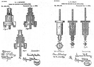
Jan. 1, 1884
|
#291,072 by Edward J. Murphy
|
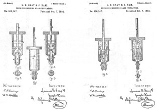
Oct. 7, 1884
|
#306,146 by Lawrence Gray
|
Oct. 7, 1884
|
#306,147 by Lawrence Gray/Joseph Ham
|
The later three patents deal with a new method of forming threads in glass
insulators and are very prominently signed by the sane patent attorney, Sylvenus
Walker. The Murphy patent was assigned to Gray and Ham which may explain why
they used the same attorney and a common witness, Charles Gooding. The first two
patents are very interesting in that they have almost identical claims and Frank
Pope was the patent attorney for the Lewis patent. For brevity, only the patent
drawings are reproduced and they follow this article.
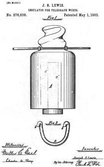
Joseph S. Lewis was from England and he obtained the patent No. 276,839
dated May 1, 1883. The Lewis patent claims were for a conical or expanding
screw-thread on the exterior to accept a new design of tie wire consisting of a
horseshoe form of rigid metal clip provided with open hooks for the purpose of gripping the
line wire (refer to the drawing of the Lewis patent). The insulator employing this
design was threadless.
Threadless insulators were popular in England and were the norm as most of the insulators used
there were
preferably cemented to the pin.
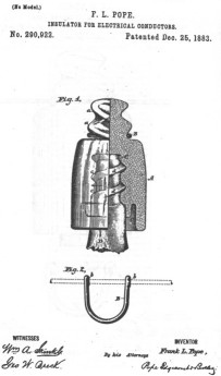
Frank L. Pope was Mr. Lewis' patent attorney as can be seen by his signature
on the Lewis patent. The Pope patent is No. 290,922 and dated December 25, 1883.
Mr. Pope evidently was quick to recognize that the Lewis patent had a few short
comings if it were to be used in the U. S. and his filing date of May 23, 1883
employing those improvements was just 23 days after the Lewis patent was
awarded. Mr. Pope used a similar drawing for his patent filing as well as text
that was word for word in many areas. His patent was designed for a threaded
insulator so the insulator could be screwed onto the pin and, with the opposing
threaded top (opposite twist to the Lewis patent), the tie wire could be secured
at the same time! Eureka! A better "mousetrap"! In all fairness, the
pitch of the screw top on the Lewis patent was totally satisfactory for
threadless insulators.
It may be appropriate here to mention some background about Mr. Pope. He was
a very prominent man in the field of telegraphy, electrical engineering and
patent law. He was first associated with electrical work when he was appointed a
telegraph operator on the American Telegraph line in 1857. A few years later, he
was a draftsman in the Patent Bureau of the office of the Scientific American
where he acquired much knowledge of patent law. In the war of the Rebellion
(Civil War), he reentered telegraph service in 1861 at Providence, RI where he
attracted the attention of Marshall Lefferts of the American Telegraph Co. who
later commissioned him to make a complete, detailed report on the company's
lines covering thousands of miles from Maine to Virginia (a two year job).
He held several patents on the construction of printing telegraphs and
electric railway signaling apparatus. He was responsible for convincing Mr.
Westinghouse of the benefits of electric power using alternating current. He
aided in the publication of the weekly trade journal "The Electrical
Engineer" and was the second president of the AIEE in 1886. Mr. Pope was
very influential and very possibly, due to his reputation, had much to do with
the success of the National Self-Binding insulator.
The Electrical Review article dated August 29, 1885 reprinted on the
following pages, publicly introduced the National Self-Binding insulator.
Illustrations 1 and 2 correctly show the insulator with reverse external threads
as detailed in the Pope patent. However, in illustrations 3 and 4, the engraver,
apparently confused , showed the external threads with the opposite twist as detailed in the Lewis patent!
|
This article is reprinted from the August 29, 1885 issue of the Electrical
Review.
The National Self-Binding Insulator.
This insulator, which is coming into
particular favor with telephone and telegraph people, is now controlled in the United States by
Messrs. Lytle & Co., of this City. The American Bell
Telephone Company have decided to adopt them for their long line work, and other
local companies are using them with very satisfactory results. This Insulator is
the invention of J. Slater Lewis, of England. and is being extensively used in
Europe. It dispenses entirety with the old and troublesome tie-wire, being so
constructed that the line-wire is applied and secured without the use of any
tools whatever, and in the shortest possible time. It can be used in any situation, whether on curves,
against walls, under bridges. on roofs or wherever
a tie-wire can he used. It is remarkably simple, durable and efficient, and may
be removed or renewed with the greatest facility. It is constructed with a
conical and expanding screw-thread upon the exterior of the upper portion,
similar in form and principle to the point of a gimlet.
The line-wire is
attached by means of a rigid wire shackle or clip, formed is the shape of a
horseshoe. the curved portion of which is adapted to encircle the body of the insulator
at the base of the conical screw portion, while each end of the clip is
made into a hook adapted to grasp the line-wire. The bell of the insulator below the point of
support of the line is given the form shown by experience to be the best.
Besides the peculiar form of attachment for the wire, the National
Insulator is provided with a perfect internal screw. It is formed by newly-invented molding
tools of peculiar form; the greater sharpness and accuracy of the thread gives a
better hold to the pin, and facilitates the operation of securing the
insulator both to the main line and to the support.
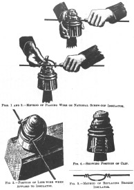
The figures 1 and 2 show the
position of the clip and line-wire when applied to the insulator.
The insulator
having been screwed on the bracket or pin, give it three complete turns backwards after it has come to
its bearing, and hook the clip on the line wire
with the ends of the hooks turned upwards, as shown In Fig. 3, then drop the clip and line wire over the top of the insulator as shown In the
same figure,
after which the insulator must be screwed down on the pin as shown in Fig. 4.
Care must be taken to see that the clip goes down the thread of the screw first
with the line wire following it, the screwing motion being continued until the insulator comes to its bearing on the pin or bracket, when the attachment will
be complete.
It will be seen that the insulator is secured
to the pin or bracket, as well as to the line wire, by a single
operation. In detaching the line wire this process is exactly reversed, the
insulator is turned the other way, the line wire going up by the groove first and
the clip following. Some linemen prefer to carry a pocket oil can, and before
screwing on the clip they apply a single drop to the point oh the clip, and also
on the line wire which rubs against the Insulator; friction is thereby avoided
and the work made easier.
To replace a broken or damaged insulator of the common
kind, it must be smashed and the pieces taken out. leaving the tie-wire attached
to the line as shown in Fig. 5. The new insulator is then screwed on the pin or
bracket as before, and the loop placed over the top of it, after which the
operation is precisely the same as illustrated in Figs. 3 and 4. After a little
practice the attachment may be made with great rapidity. |
Medium Image (47 Kb)
Large Image (147 Kb) |
Another interesting article, reprinted below, is from the Electrical Review
date January 17, 1885 where it states that the tools to make the new
"Lewis" insulator were about ready. No mention of the "Pope"
insulator. Note that the manufacturing facility was in Haverhill, Mass.
|
- - - - - - - - - - -
-
In Mr. Duxbury's office I met Mr. Lytle, who was down from
Boston on business. He tells me that work on the new insulators at Haverhill
is
progressing favorably; that the tools for making the new English (Lewis) "screw
top" insulators are about ready, ant that they expect to turn out a big lot
soon. By the way, a funny thing. Insulators is England are made of earthenware,
glazed. They "come high" over there -- not far from sixteen cents each.
They are made in a lathe, fired, then glazed, then fired again and are such
handsome pieces of pottery that one wonders they are not put up in velvet-lined
cases like Sevres cups. Why are they made of earthenware? Because in England, you
know, we always use iron pins -- not the wooden things you stick up in this country,
don't you see? Now, if we put on glass, the sun shines through it and don't heat
it. but it does heat the iron, you know, expands it, and cracks the
glass.
But if we use earthenware; don't you see, the sun can't do it. you know. Poor
things, it never occurred to them to use opague glass; simply because they
never had used opaque glass; but I am of the opinion that when Mr. Lytle
gets over there with a few thousand screw-top insulators, made in one motion with a
perfect inside thread, and of a beautiful white glass that the sun can't shine
through, any more than it can through a piece of iron, and offers them at less
than one-half what it costs the manufacturers over there to turn out their hand-made
ceramic specimens, the folks will wake up to the idea that "those
blasted Yankees'.' still have an idea or two that they have not as yet had any conception
of. By the way, Mr. Duxbury tells me that he has tried some of the new insulators
of the "pony" size, and likes them very much indeed.
- - - - - - - - - - |
The National Insulator Co. referred to it as the Lewis insulator even though
the Pope patent was the one used for the final design -- internal threads,
opposite twist to the external thread and horseshoe form of metal clip. An
apparent close association with the company by Mr. Lewis may be why the
insulator carried his name.
Medium Image (52 Kb)
Large Image (139 Kb)
Medium Image (50 Kb)
Large Image (140 Kb)
Medium Image (74 Kb)
Large Image (201 Kb)
Medium Image (57 Kb)
Large Image (154 Kb)
|

)
)